Reversible Data Embedding Using a Difference Expansion (Tian, 2003)
Jun Tian’s difference expansion embeds a payload, meaning hidden data, into a digital image while allowing the original image to be restored exactly. It expands selected differences between pixel values and carries the information needed to reverse the changes inside the image. Tian motivates reversible embedding with medical and military imagery, where access to the original data matters even when changes are visually imperceptible. The method uses redundancy in image content to create storage space while limiting distortion. Tian, Reversible Data Embedding Using a Difference Expansion (2003).
Why must the original image be recoverable?
Embedding changes pixel values. Tian addresses applications where even a slight change can affect the information carried by an image. Recovering a hidden message alone would leave those changed pixels in place.
“The motivation of reversible data embedding is distortion-free data embedding [1].”
— Tian (2003), Section I
Reversibility requires message extraction and exact image restoration. Capacity is how much data fits; distortion is the image change. The authors assess capacity, visual quality and computational complexity. Recovery information shares space with the message. Embedding a message authentication code supports self-authentication without separate metadata. This code is calculated from content using a secret key.
Why transform pixel pairs into an average and a difference?
Section III-A uses a reversible integer transform, also called the integer Haar wavelet transform or S transform. It maps each pixel pair to a rounded average and a signed difference. Similar pixels give small differences, motivating neighboring-pixel pairing.
For pixels x and y, the integer average is l and the difference is h. Equations (1) and (2) are:
l = floor((x + y) / 2)
h = x - y
x = l + floor((h + 1) / 2)
y = l - floor(h / 2)
The function floor rounds toward the smaller integer, including for negative inputs. The inverse restores the pixels exactly. The encoder embeds data; the decoder extracts it and restores the image. Tian permits horizontal, vertical or key-based pairing. Both operations use matching pairing and reading order.
How does expanding a difference store a bit?
Difference expansion adds a new least significant bit, or LSB, to the difference. The LSB is its final binary digit. For a message bit b, either zero or one, the embedding and extraction rules are:
h_embedded = 2 * h + b
b = h_embedded - 2 * floor(h_embedded / 2)
h = floor(h_embedded / 2)
The average remains unchanged. The inverse transform produces the embedded pixels. Section II explains that the added binary position carries the message while integer division recovers the earlier difference.
For example, pixels 206 and 201 have average 203 and difference 5. Embedding a one makes the difference 11 and the pixels 209 and 198. The final binary digit, called the least significant bit or LSB, gives back the message bit. Rounding half of 11 down restores difference 5 and then the original pair. Embedding a zero instead gives difference 10 and pixels 208 and 198.
How does the encoder prevent pixel overflow?
An expanded difference can reconstruct a pixel outside its permitted range. Section III-A derives bounds for eight-bit grayscale pixels, ranging from 0 to 255. Equation (3) and the expansion test become:
limit(l) = min(2 * (255 - l), 2 * l + 1)
valid difference: abs(h) <= limit(l)
expandable: abs(2 * h + b) <= limit(l), for both b = 0 and b = 1
changeable: abs(2 * floor(h / 2) + b) <= limit(l), for both bits
An expandable difference safely accepts either bit through expansion. A changeable difference safely accepts replacement of its existing LSB. Testing both bits makes eligibility independent of the message. The authors leave nonchangeable differences untouched rather than clipping reconstructed pixels, which would discard restoration information.
Why use every changeable difference as the embedding area?
The decoder needs to find the hidden stream before it can read the map describing expanded pairs. Expansion can change whether a difference is expandable, so testing expandability in the received image would not recover the original selection.
Section III-B establishes the property used instead: expandable differences are changeable, expanded differences remain changeable, and replacing a changeable difference’s LSB preserves changeability. The authors therefore use every changeable difference as an embedding position. Selected pairs carry bits through expansion; other changeable pairs carry bits through LSB replacement. The same positions remain identifiable at decoding.
“Note that we do not examine expandability at the decoder.”
— Tian (2003), Section IV
The decoder reads LSBs in scanning order to recover the map.
Why carry a location map and original low bits?
A location map distinguishes expansion from replacement. It is a binary image with one entry per pair: one for expansion, zero otherwise. Section III-C compresses it with JBIG2, a lossless binary-image compression method, or run-length coding, which records lengths of repeated values.
The complete encoding sequence is:
- Pair pixels, calculate averages and differences, and fix their reading order.
- Separate expandable zero and minus-one differences, other expandable differences, other changeable differences, and nonchangeable differences.
- Select expansions and compress their location map.
- Collect the original low bits needed to undo replacements.
- Concatenate the compressed map, saved low bits and payload; embed that stream across changeable positions.
- Apply the inverse transform to reconstruct the embedded image.
The payload includes the image’s authentication hash, a fixed-length value calculated from its content. Map compression and saved-bit overhead reduce the space available for additional data.
Why always expand zero and minus-one differences?
Saving every overwritten low bit would consume space. The authors reserve expandable differences of zero and minus one for expansion. This rule lets the decoder infer some original bits without storing them.
If the location map marks a received difference as unexpanded, a value of zero or one identifies an original difference of one. Otherwise an original zero would have been expanded and marked in the map. Likewise, a received minus-two or minus-one difference with an unexpanded map entry identifies an original minus two. Other overwritten low bits must be saved.
Section III-D derives the payload budget from selected expansions, these inferred bits, and the compressed map length. A single embedding layer has a payload capacity below 0.5 bits per pixel. Bits per pixel, abbreviated bpp, divides payload length by image pixel count.
Why select differences with a magnitude threshold?
Expanding a large difference causes larger pixel changes. Section III-D relates the distance between original and embedded pixel pairs approximately to the magnitude, or absolute size, of their difference. The approximation comes from integer rounding. To reduce mean squared error, the average squared pixel change, Tian selects small differences first.
The encoder starts with a small magnitude threshold and raises it until the payload and recovery data fit. It may then remove selected differences near the threshold to fine-tune capacity. Changing the selection also changes the compressed map length.
The authors offer another selection criterion called hiding ability. It measures how many replacement values would remain within the pixel bounds. Large hiding ability favors averages near mid tone and differences near zero. The paper uses this as a selection guide while embedding one bit per selected difference.
How does decoding restore and authenticate the image?
Reading the hidden stream is only the first step. Section IV decodes the map first; the compressed map’s end marker identifies where its bits stop. The decoder halves differences marked as expanded. For other changeable differences, it infers the special low bits or reads saved bits from the stream. The remaining stream holds the payload.
The inverse transform restores pixel pairs. Authentication requires the embedded hash to match a hash of the restored image exactly. The authors state that tampering will most likely cause an earlier error, such as invalid compressed-map syntax or an expansion marker at a nonchangeable position.
For multiple layers, a header records the preceding layer’s pairing pattern. Decoding proceeds in reverse layer order until the header identifies the original image or tampering is discovered.
Why repeat embedding and preserve local averages?
A single layer has limited capacity. Section III-D allows another payload to be embedded into an already embedded image, or one payload to be split across layers. Pairing may change between layers. The authors state that each layer’s capacity gradually decreases as pixel redundancy is consumed.
Keeping integer averages also supports reduced-resolution viewing. With pairing inside each two-by-two pixel block, its mean is preserved apart from integer-rounding errors. Halving both dimensions through block averaging therefore preserves reduced-resolution content apart from rounding. This motivates the half-resolution fidelity example. Exact restoration still uses the intact embedded image.
All parts of the method
The encoder turns pixel pairs into averages and differences, selects safe expansions, and packs a compressed map, saved low bits and payload into the changeable differences. The inverse transform produces the embedded image. The decoder finds those same changeable positions, reads the map, reverses expansion and replacement, and reconstructs the image. An authentication hash tests the restored content. Repeated embedding adds a pairing header so layers can be removed in reverse order.
What experiments did the authors run?
The authors test payload versus image error, compare capacity and distortion with earlier methods, and examine a half-resolution preview after repeated embedding.
Payload size and embedded-image quality
Section V embeds and decodes actual bitstreams generated by rounding MATLAB random values to integers. The authors test grayscale images from Waterloo BragZone and the JPEG 2000 test collection. Detailed results use eight-bit, 512×512 Lena.
Peak signal-to-noise ratio, or PSNR, expresses image error in decibels, abbreviated dB. It compares the maximum pixel value with the root mean squared pixel error. Higher PSNR means less average squared error. Table II reports:
| Payload bits | Rate (bpp) | PSNR (dB) |
|---|---|---|
| 39566 | 0.1509 | 44.20 |
| 63676 | 0.2429 | 42.86 |
| 84066 | 0.3207 | 41.55 |
| 101089 | 0.3856 | 40.06 |
| 120619 | 0.4601 | 37.66 |
| 141493 | 0.5398 | 36.15 |
| 175984 | 0.6713 | 34.80 |
| 222042 | 0.8470 | 32.54 |
| 260018 | 0.9919 | 29.43 |
| 377869 | 1.4415 | 23.99 |
| 516794 | 1.9714 | 16.47 |
Source: Tian (2003), Table II.
Figures 1, 2 and 3 show the bolded payloads. The authors describe degradation around 44 dB as almost imperceptible and state that the original can be completely restored. At the largest displayed payload, they report preserved image content. They attribute mild sharpening in mid-tone regions to increased difference magnitudes.
Capacity and distortion against earlier methods
Figure 4 compares Lena results with RS lossless embedding and the selective embedding extension of generalized LSB, abbreviated G-LSB. RS uses pixel groups; G-LSB compresses quantization residues, values left after reducing pixel precision. The authors select the G-LSB extension for its capacity-versus-distortion results among the implementations they discuss.
The operation varied is embedded payload size. PSNR measures the resulting distortion. The authors report that, for an equal payload length, difference expansion gives about 2 to 3 dB higher PSNR than these methods. They also report that G-LSB capacity generally stays at or below 1 bpp except for images with large, very smooth regions, while difference expansion can exceed 1 bpp. RS capacity is lower than both. The authors use PSNR because a universal image-quality measure is lacking.
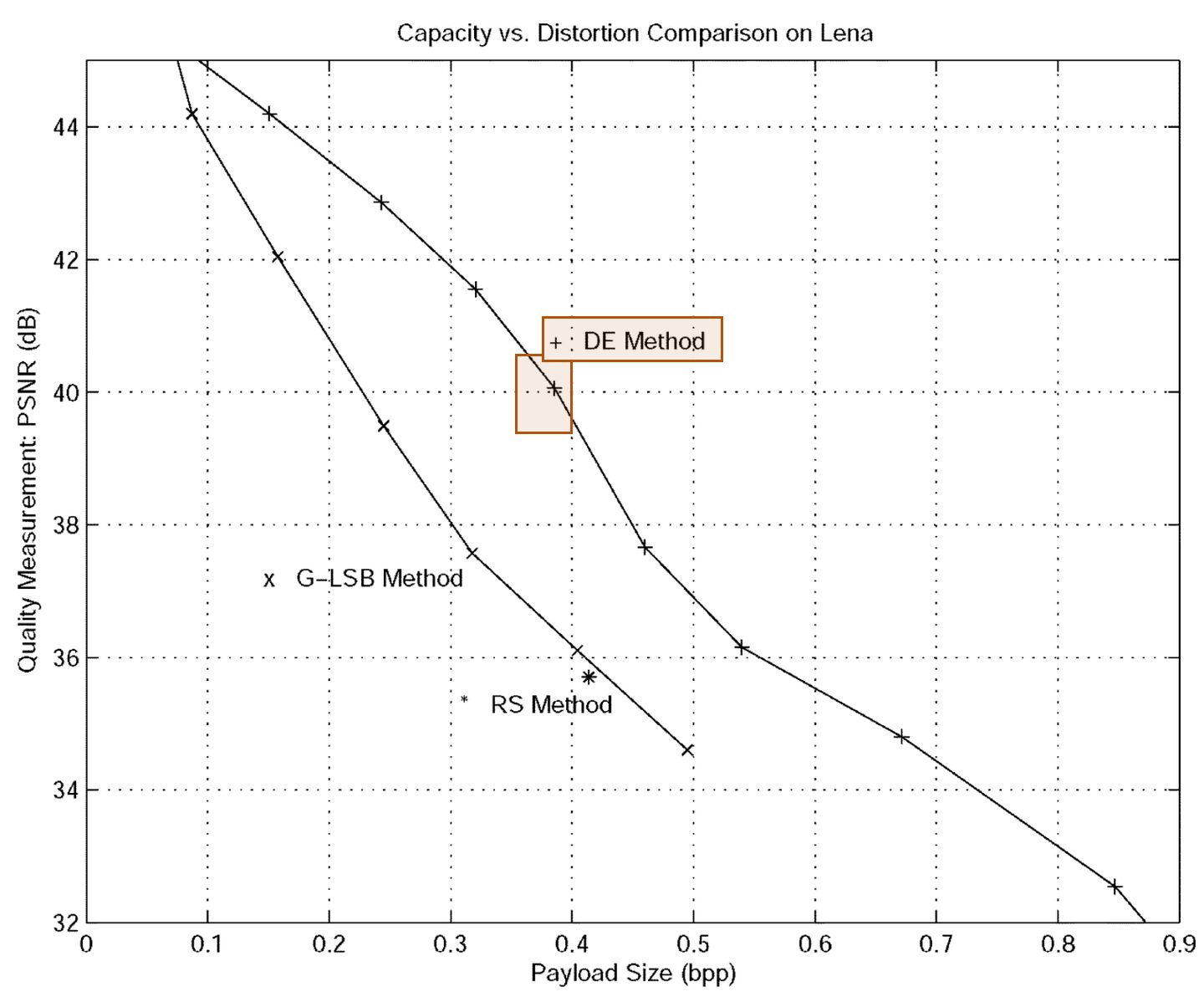
Tian (2003), Figure 4. DE capacity and distortion curve.
Half-resolution fidelity after multiple layers
The high-payload Lena image in Figure 3 uses repeated embedding with alternating horizontal and vertical pairing. A 2×2 mean filter replaces each block by its mean, producing the 256×256 preview in Figure 5. The authors describe its visual quality as imperceptible from the original at that resolution. Section III-D qualifies average preservation with integer-rounding errors.
Our test: payload size and exact pixel recovery
| Setting | Value |
|---|---|
| Images | Airplane; Boat |
| Pixels | 512×512; 8-bit grayscale |
| Pairing | Horizontal neighbors |
| Data | Random user bits |
| Test | Embed, save, extract, restore |
We re-implemented the method ourselves because we did not find the author’s code. Our code and numeric results are on GitHub.
The inputs are USC-SIPI Airplane and Boat. Both retain their original dimensions after grayscale conversion.
User payload means the random message alone. The location map, saved low bits, a 16-bit zero header marking the first embedding pass, message length, image digest, and unused stream space all consume embedding capacity. None are counted as user data. For each message size, selection starts with small differences and increases the magnitude threshold until the complete stream fits.
The panels show the original, the embedded output, an absolute difference, and the restored image at 98,304 user bits, or 0.375 bits per pixel. Absolute difference means the size of each pixel change without its sign. The display multiplies it by 16 and limits brightness to 255, making small changes visible.
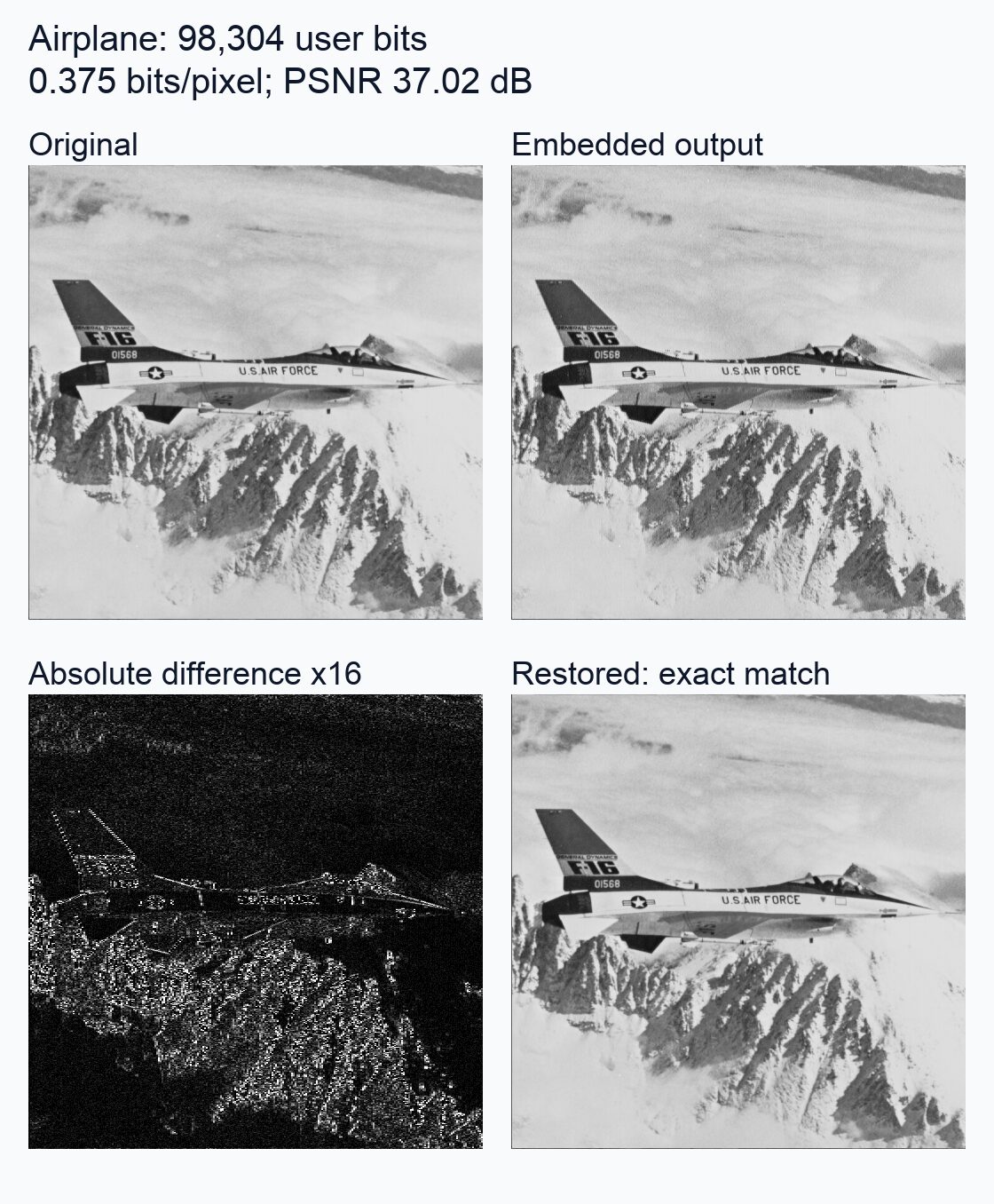
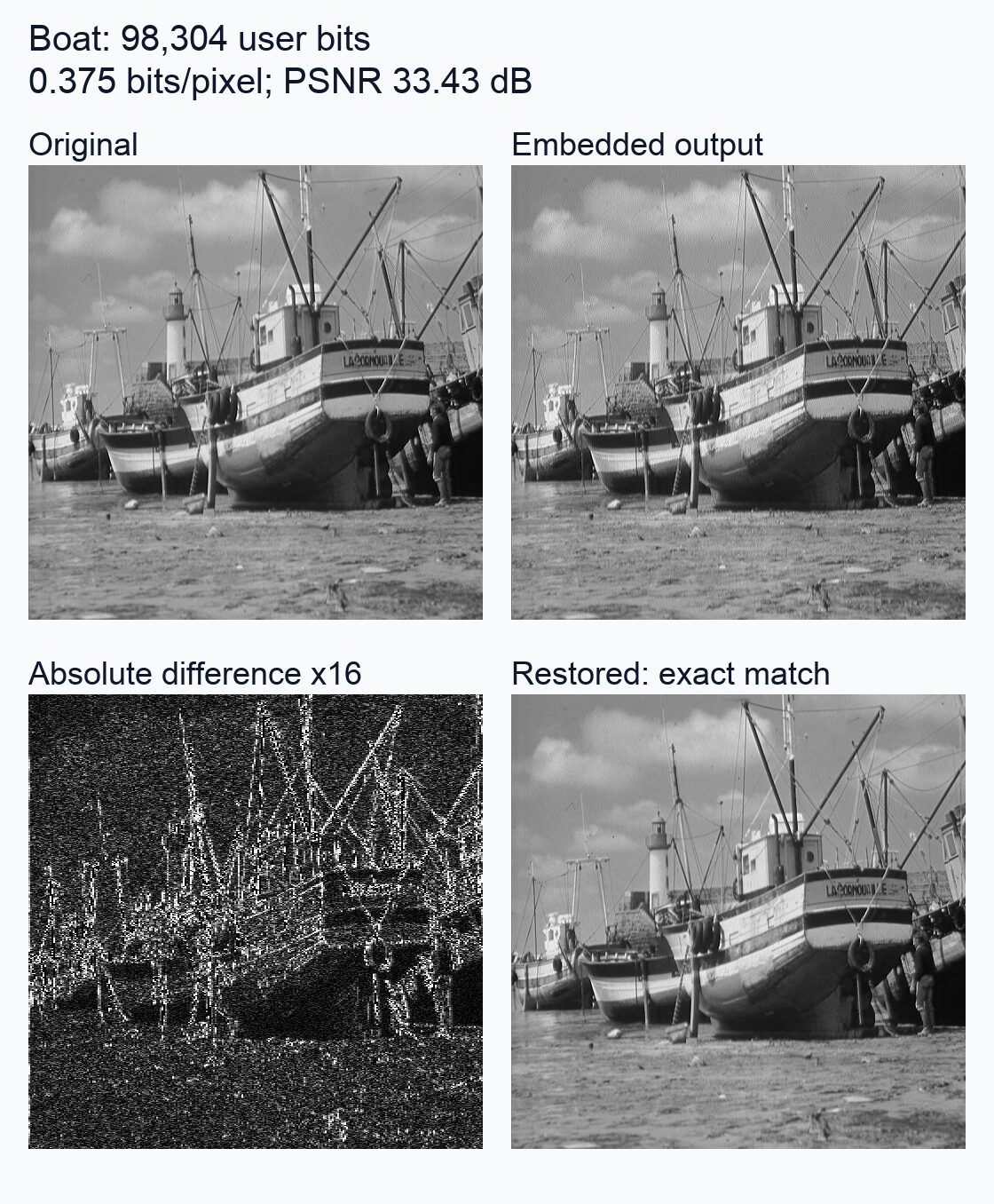
The chart plots user payload against PSNR between the original and embedded pixels. The table gives the same measurements, with PSNR rounded to two decimal places.
| User bits | bpp | Airplane | Boat |
|---|---|---|---|
| 16,384 | 0.0625 | 45.38 | 38.35 |
| 32,768 | 0.1250 | 44.15 | 37.65 |
| 65,536 | 0.2500 | 41.03 | 35.88 |
| 98,304 | 0.3750 | 37.02 | 33.43 |
Across these settings, increasing the message size reduced PSNR on each image. We measured 0 payload bit errors and 0 restored pixel errors across all settings: decoding each embedded image returned the complete message and every original pixel.
Each image and message size uses its own repeatable sequence of random bits. Zero bits fill unused embedding space; they use capacity but do not count as message data.
| Item | Setting |
|---|---|
| Preparation | Grayscale conversion; no resizing |
| Scan | Across each row, top to bottom |
| Selection | First sufficient integer magnitude threshold |
| Map | Run lengths; separate codes for zeros and ones |
| Framing | 16-bit header; 32-bit user length |
| Digest | SHA-256; 256 bits; unkeyed |
Conditions and limits
The decoder needs the same pairing and reading order, with encoded pixel values intact. Tian describes reversible embedding as fragile: manipulation or lossy compression prevents original-content restoration when authentication fails. The map and saved low bits must be decoded successfully before pixels can be recovered.
Our test saves embedded images as lossless PNGs and applies no compression loss, resizing, cropping or other image changes. It uses horizontal pairing, a single embedding pass, and run-length map compression. We did not test authentication with a secret key, encryption, repeated embedding or reduced-resolution appearance.
Implementation details
Our implementation keeps every pair selected at the first sufficient integer threshold without fine-tuning individual selections. It fills unused stream space with zeros and records the user-message length separately. Map compression uses separate run-length codes for zeros and ones. The digest is calculated from pixel bytes without a secret key and does not identify the creator.
References
- Tian, J. (2003). Reversible Data Embedding Using a Difference Expansion. IEEE Transactions on Circuits and Systems for Video Technology, 13(8), 890–896. DOI: 10.1109/TCSVT.2003.815962.
- USC-SIPI Image Database. Miscellaneous volume. Catalog, Airplane, 4.2.05, and Boat, boat.512.
- Our re-implementation code and numeric results: GitHub, tian-2003-difference-expansion.