A Digital Watermark (van Schyndel et al., 1994)
Van Schyndel and colleagues embed a digital watermark, a hidden message, in an image by manipulating its least significant bit, or LSB. This is the lowest binary digit of a pixel’s brightness value. Their methods either replace that digit with a code pattern or add the pattern to the image. The authors envisage carrying authentication or authorisation codes and information needed to interpret the picture. They seek visually undetectable changes and accurate message recovery for image tagging, copyright protection and controlled access. R. G. van Schyndel, A. Z. Tirkel, and C. F. Osborne, A digital watermark, ICIP (1994).
Why hide the message in the lowest bit?
The authors want an image to carry identifying or interpretive information while retaining its visible contents. Their starting problem is embedding an undetectable message and extracting it accurately. They choose direct pixel manipulation: an eight-bit grayscale pixel holds a brightness from 0 to 255, and its LSB separates adjacent even and odd values. A bit plane collects the same binary digit from every pixel.
Section 2 argues that hardware imperfections or quantisation noise often already corrupt this plane. Quantisation means representing brightness with a finite set of levels. The authors therefore regard sacrificing the LSB as having limited significance in many imaging systems. They qualify visibility by image content: a pattern can become visible across large areas with little intensity variation. Their rationale links the embedding location to expected image noise and to the need to preserve the picture’s brightness range.
Why use an extended m-sequence and encode its phase?
The decoder needs a pattern it can distinguish from image content. An m-sequence is a maximal-length binary sequence generated by shifting stored bits and combining selected bits. Autocorrelation compares a sequence with shifted copies of itself. The authors choose m-sequences for their balance, random appearance and concentrated autocorrelation peak. They reject Costas arrays, two-dimensional patterns they studied, because the patterns are sparse.
The sequence length and the extended length are:
ordinary length = 2^n - 1
extended length = 2^n
Here n is the number of stored generator bits. Extension fits a power-of-two image dimension and creates a null, or zero response, around the main autocorrelation peak. Phase means the sequence’s starting position within its repeating cycle. The authors choose phase to carry the message for simplicity; changing the sequence or using its complement, which flips every bit, are other choices they discuss.
“For simplicity, we have chosen to encode the water mark by the choice of m-sequence phase.”
— van Schyndel et al. (1994), Section 1
How does replacement make room for the code?
Directly replacing brightness bits sacrifices image information. Section 3 first compresses the image’s eight-bit brightness representation to seven bits through adaptive histogram manipulation. A histogram counts pixels at each brightness. A compensating mapping then restores the dynamic range, the span of available brightness values. The authors describe the prepared image as practically indistinguishable from the original.
The replacement path proceeds row by row:
- Reduce brightness precision using the image histogram.
- Map the reduced levels across the brightness range, freeing the LSB.
- Select a sequence phase for the row’s message value.
- Write the shifted sequence into the row’s lowest-bit plane.
- Extract that plane and compare it with the stored reference to recover the phase.
For illustration, use the 7-bit sequence 1110010 from a 3-bit generator; the method uses longer sequences, with 512 bits in our test. Shifting it right by 3 gives 0101110. Writing those bits into prepared even pixels 100, 102, 104, 106, 108, 110, 112 gives 100, 103, 104, 107, 109, 111, 112. Mapping extracted and reference bits to minus one or plus one gives circular correlation 7 at shift 3 and −1 elsewhere.
Why add the pattern instead of replacing a bit plane?
The authors also seek an embedding operation that preserves a linear relation between image and watermark. Linear addition adds the binary pattern to the brightness values. The abstract argues that this permits some processing, such as averaging, while retaining a recoverable watermark. The detector must examine the complete brightness pattern, making extraction dependent on image content.
In words and symbols, with x the image brightness, b the selected binary code and y the marked brightness:
y(i) = x(i) + b(i)This expresses the addition operation described in Section 3. The authors attribute added security to an attacker having to perform the decoding operations without prior knowledge. Their implementation performs decoding off-line, which they identify as its principal disadvantage. Partial correlation between image and code also causes recovery errors. Correlation here means multiplying corresponding received and reference values and summing them; an image structure can contribute its own response at a candidate phase.
Why filter correlation before choosing a message?
An image can mask the watermark’s correlation peak. Section 3 describes a sharp message peak superimposed on a significant, slowly varying background. A differential filter combines nearby correlation values to separate this sharp feature from the background. The authors tested different filter lengths and repeated filtering, selecting this kernel for their image and sequence size:
kernel = [-1, -1, 4, -1, -1]
F(k) = 4 R(k) - R(k-2) - R(k-1) - R(k+1) - R(k+2)
R(k) is correlation at phase k; F(k) is its filtered value. The equation writes the stated kernel as a sum. Circular sequence shifts wrap at the row ends. Threshold detection accepts a candidate when its response exceeds a chosen level. The authors describe separating image and message peak distributions as evidence that thresholding is feasible. Their histogram analysis suggests reducing brightness from eight bits to five should permit successful detection. They also suggest longer sequences or improved filtering and detection algorithms.
All parts of the method
The message determines the sequence phase for each row. Replacement prepares brightness levels, inserts the pattern in the LSB and compares extracted bits with a reference. Addition inserts the pattern into full brightness values, correlates each received row with the reference, and filters the response to locate message peaks. The authors’ threshold proposal uses the separation between background and message responses. The diagram presents the two decoding paths, including the largest-peak choice used by our addition decoder.
What experiments did the authors run?
The authors examine embedding and visibility, filter selection and threshold separation, false detections, simultaneous messages, and recovery of repeated text.
Embedding and visibility
Section 3 reports experiments on 512-by-512, eight-bit grayscale images, encoded line by line with extended sequences of length 2^9. For replacement, the operation reduces brightness precision to seven bits and maps the levels back across the dynamic range. The authors describe this prepared image as practically indistinguishable from the original. For addition, they describe a composite image before and after watermark insertion and an enlarged detail, referenced as Figure 4(a–c).
The authors qualify invisibility by the expectation of low-level Gaussian noise, meaning random intensity variation with a bell-shaped distribution. Section 2 states that m-sequence encoding and one-bit Gaussian noise are statistically indistinguishable, while large areas of small intensity variation can reveal the changes. Section 3 says computer-generated images typically fall outside the stated noise condition.
Filter selection and threshold separation
For addition decoding on 512-by-512 images with a nine-bit sequence generator, the authors tested impulse-response filters of various lengths, in single-pass and multiple-pass configurations. An impulse response specifies the weights used to combine neighboring correlation samples. They report optimum results for the kernel [-1, -1, 4, -1, -1].
Section 3 describes image and message correlation histograms in Figure 3(a–b) as separated sufficiently to support threshold decoding. Histogram analysis suggests a three-bit dynamic-range reduction, from eight bits to five, should permit successful threshold detection. A sequence of length 2^15 or improved filtering is proposed as an alternative. The authors argue that these alternatives should similarly suppress interference from image content.
False positives and false negatives
The authors investigate image content’s effect on correlation for the same row-based addition method. A false positive is an image response accepted as a watermark; a false negative is a message response that the detector misses. They attribute imperfect extraction to partial correlation of the image data with the encoding sequence. Their account treats image-dependent background responses as the reason for filtering and brightness compression.
Simultaneous messages
Section 3 also describes adding two distinct messages to the same image. Each message uses a different m-sequence, and both patterns are added to the brightness data. The authors investigate mutual interference and recovery ability. Their stated application is an image carrying separate hospital and radiologist watermarks. They examine how each added sequence affects recovery of the other message.
Repeated-text recovery
The authors describe filtered correlation for an image with and without its added mark in Figure 4(d). Message peaks appear as single white dots whose positions determine letters. The displayed message is “aabbccAABBCC ” repeated four times. The result connects sequence phase to recovered characters in the marked composite image. The authors identify image dynamic range and the correlation output as the main difficulties in their conclusions. Section 5 assigns cropping, skew, rotation and translation experiments to future work; the abstract describes JPEG and MPEG compression compatibility as potential.
Our test: Which row values survive JPEG?
We re-implemented the method ourselves because we did not find the authors’ code. Our code and numeric results are on GitHub.
| Setting | Value |
|---|---|
| Images | Airplane; Boat |
| Preparation | 512×512, eight-bit grayscale |
| Message | Nine message bits per row |
| JPEG quality | 100, 95, 85, 75, 50 |
The inputs are USC-SIPI Airplane and Boat. Both methods receive the same message values. JPEG quality is the encoder setting that controls preservation of image detail.
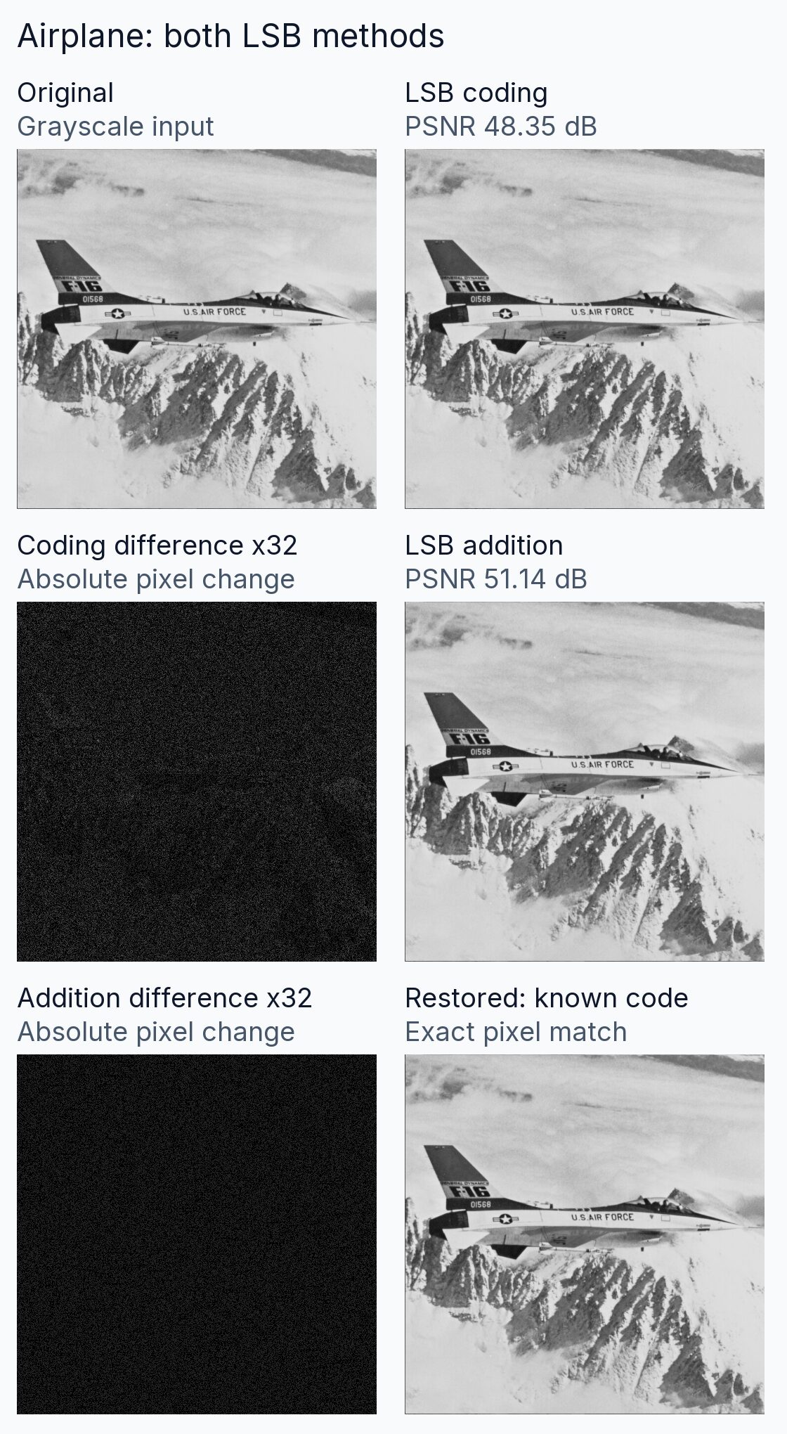
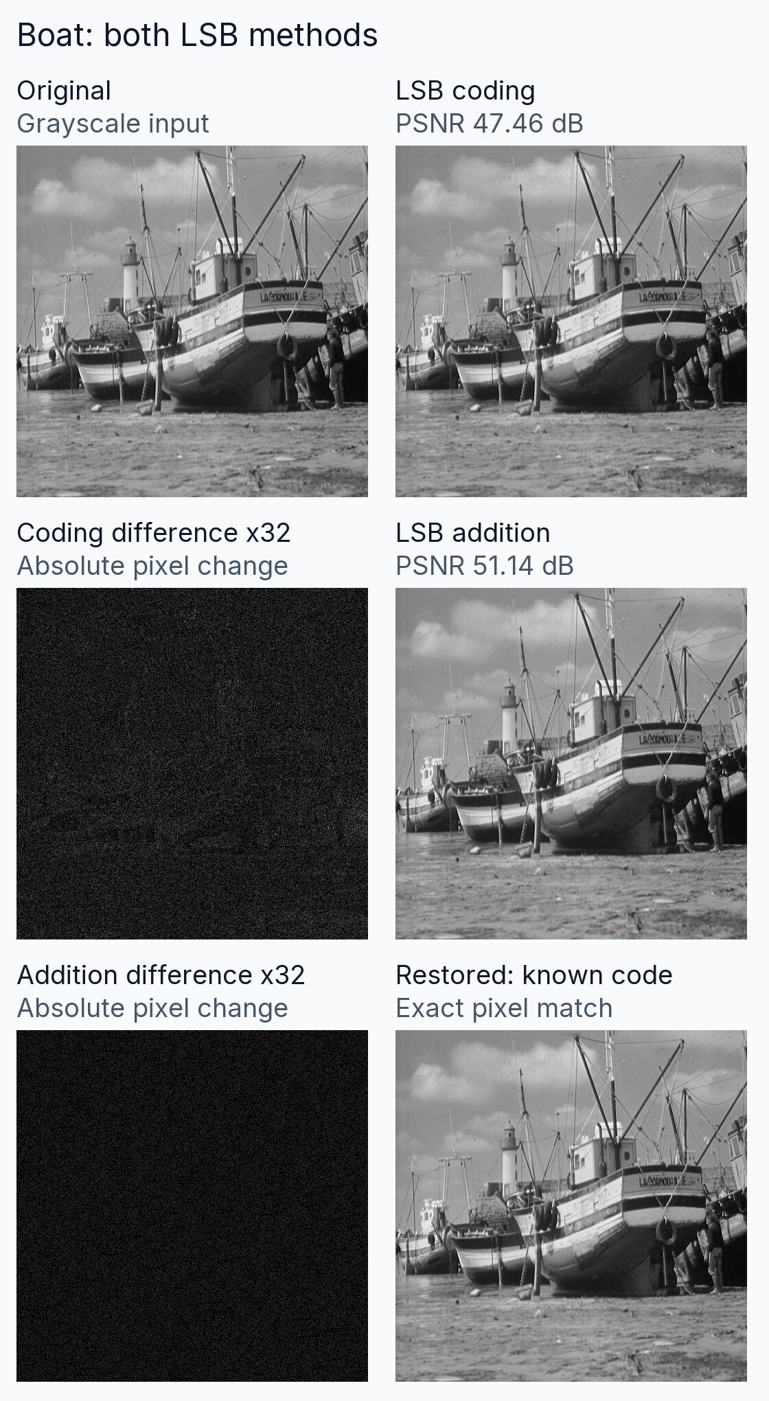
The panels show each original, both marked outputs, and absolute pixel differences amplified 32 times. Absolute difference is the size of a brightness change without its sign. Peak signal-to-noise ratio, or PSNR, expresses average squared pixel error on a logarithmic scale in decibels, abbreviated dB. Message bit accuracy is the percentage of recovered message bits that match their inputs. Row recovery requires the entire phase value to match.
| Image / method | PSNR dB | Bits % | Rows % |
|---|---|---|---|
| Airplane / coding | 48.35 | 100.00 | 100.00 |
| Boat / coding | 47.46 | 100.00 | 100.00 |
| Airplane / addition | 51.14 | 54.62 | 10.16 |
| Boat / addition | 51.14 | 52.00 | 3.91 |
These are the clean-image results. Subtracting the known inserted pattern restored every pixel in both addition images. Restoration uses the saved pattern. LSB coding replaces brightness information, so removing its code cannot restore the original.
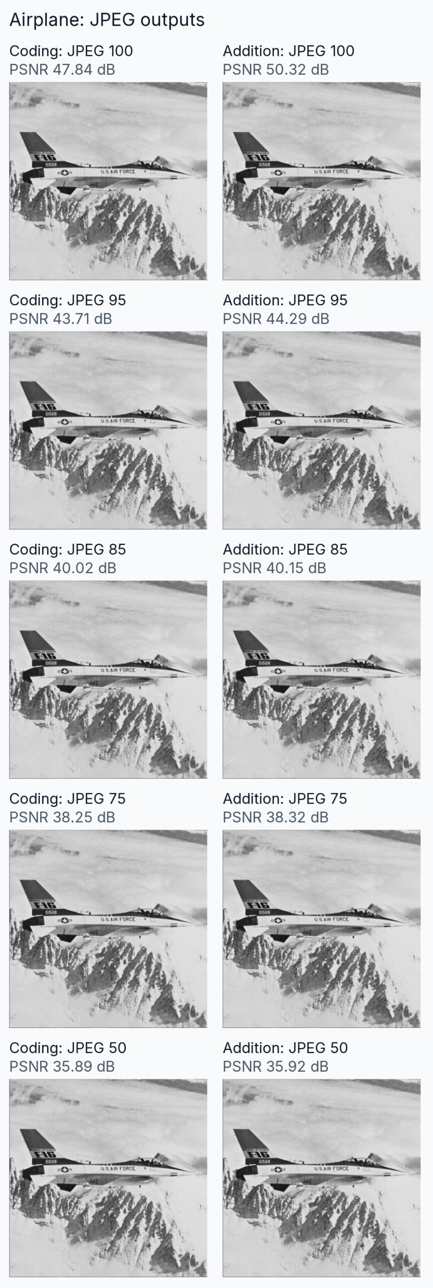
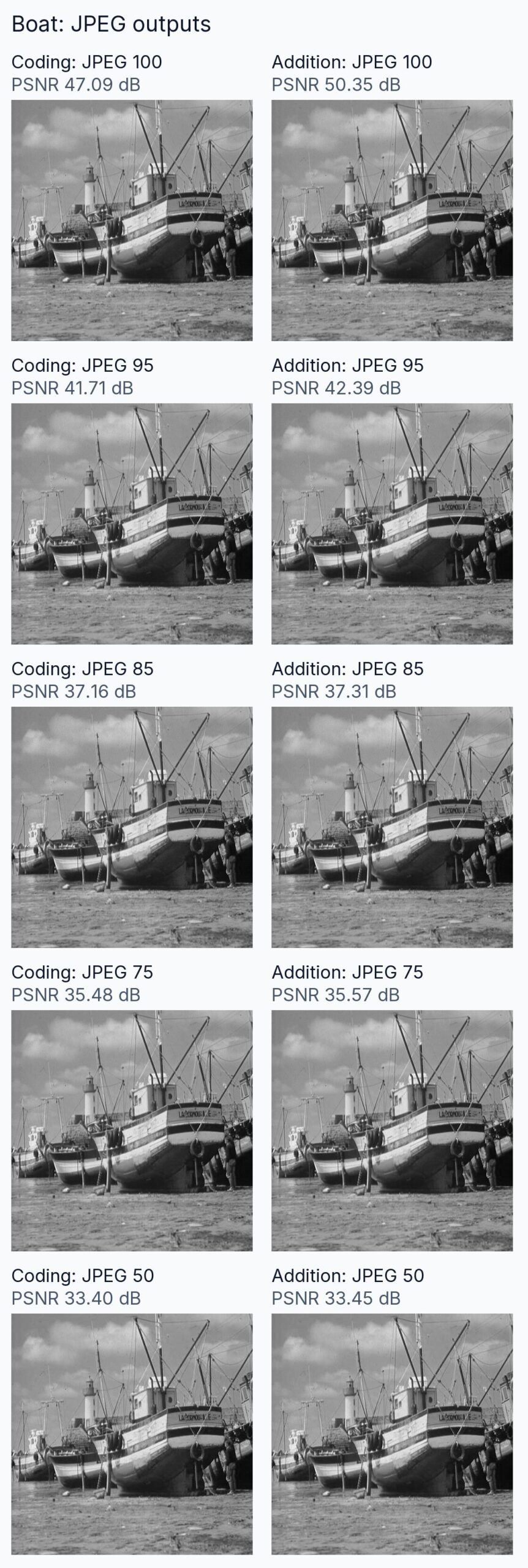
The charts show exact row recovery, including the clean outputs. Coding recovered every row at JPEG quality 100 on both images. At quality 95, row recovery was 0.59% for Airplane coding and 0.00% for Boat coding. Addition recovered 3.52% and 2.34% respectively at that quality.
Our coding preparation merges adjacent histogram groups and maps their averages to even brightness values before insertion. Addition uses full grayscale values, one filter pass, and the largest filtered value without a detection threshold. Values above 255 are limited to 255; no tested addition exceeded 255. Restoration subtracts the saved inserted pattern before JPEG compression.
| Item | Setting |
|---|---|
| Random message starting value | 199409 |
| Preparation | Grayscale conversion; no resizing |
| Sequence | Nine stored bits, initially all ones; each new bit is the oldest bit exclusive-or the fifth-oldest bit |
| Histogram | Up to 128 groups; even representatives |
| Addition | Binary 0 or 1; saturate at 255 |
| JPEG | Qualities 100, 95, 85, 75, 50; grayscale |
Exclusive-or returns a set bit when its input bits differ.
Conditions and limits
Decoding requires the reference sequence, its bit convention and the correct row boundaries. The authors tie visibility to expected low-level image noise and describe addition recovery as dependent on image content. They identify retaining the brightness range and separating correlation peaks as practical difficulties. They propose adaptive filtering and geometric-distortion experiments as future work. Our test keeps image dimensions and alignment fixed and uses photographs processed by JPEG compression. Its decoder selects the largest filtered response; the paper discusses threshold detection.
Implementation details
The same preparation and decoder settings apply to both photographs. The histogram limit controls brightness reduction in the coding path. The filter uses wraparound at the ends of the correlation sequence. Our restoration operation uses the saved insertion pattern. The authors describe hardware implementation in programmable gate arrays, integrated circuits whose logic can be configured, as a route to on-line, real-time execution.
References
- van Schyndel, R. G., Tirkel, A. Z., and Osborne, C. F. (1994). A digital watermark. Proceedings of the IEEE International Conference on Image Processing, volume 2, pp. 86–90. DOI: 10.1109/ICIP.1994.413536.
- USC-SIPI Image Database. Miscellaneous images: Airplane, 4.2.05 and Boat, boat.512. University of Southern California. Database catalog.
- Our re-implementation code and numeric results: GitHub, vanschyndel-1994-digital-watermark.